
With the rapid development of mobile communications, radio frequency coaxial cables used in base station systems and indoor distribution systems have also become more and more widely used. Radio frequency coaxial cables are usually used in higher frequency bands, such as the 900MHz, 1800MHz used by 2G, 800MHz used by CDMA, and the frequency above 2000MHz used by 3G. Nowadays, mobile communication is moving towards the third-generation (3G) and fourth-generation (4G) mobile communication networks. my country is also about to enter the era of 3G networks. Among the various electrical parameters of radio frequency coaxial cables for mobile communications, attenuation is an important indicator. The use frequency of 3G network will reach above 2GHz, which puts forward higher requirements on the electrical performance of the coaxial cable, that is, lower attenuation. How to ensure the attenuation of the cable in the design and production is quite important.
The main factors affecting the attenuation of radio frequency coaxial cables
1.1 “The influence of raw materials on attenuation
The raw materials that affect the attenuation in the RF coaxial cable mainly include internal
Materials such as conductor, insulation and outer conductor. Due to the high transmission of coaxial cable
The skin effect and proximity effect will be generated when the frequency current is high, and these effects
As the transmission frequency continues to increase, it increases significantly, resulting in more current
More and more towards the surface of the conductor, and along the outer surface and outer surface of the inner conductor
Transmission on the outer surface of the conductor [1], so it transmits at 3GHz and below
In the frequency band, the surface quality of the conductor, especially the surface quality of the inner conductor is the same
The influence of the transmission attenuation of the shaft cable is particularly serious.
Severe oxidation or other quality problems, which will cause the coaxial cable
The attenuation of the conductor rises sharply, so the control of the conductor surface quality is particularly important
want.
When transmitting at a lower frequency, relative to the inner and outer conductors, the insulation is attenuated
The impact of reduction is smaller, but as the frequency increases, its impact continues to increase
Large, when reaching the 2GHz frequency band, the attenuation of the medium cannot be ignored. Depend on
The insulation layer basically adopts a foamed structure. From the actual situation,
Foaming degree is the most important factor that affects the cable dielectric attenuation, characteristic impedance and other parameters.
major factor. 1.2 The influence of standing wave on attenuation
Due to the structure of the cable itself and the inevitable in the production process
Inhomogeneity, the voltage standing wave ratio must exist, and there will be transmission in radiation
The energy in the high-frequency coaxial cable, part of it passes through multiple transmissions—reversely
Shooting, the phenomenon that eventually returns to the launching end. This loss of energy‚
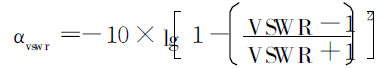
It is also a factor that affects the attenuation of the cable, which forms the voltage standing wave ratio (reflection)
The additional attenuation caused by αvswr. The relationship between voltage standing wave ratio and αvswr is as
1.3 The influence of cable structure on attenuation
Figure 1 is a schematic diagram of the structure of a radio frequency coaxial cable.
DOI: 10.16105/j. cnki. dxdl. 2008.06.003
The insulating layer is composed of skin-foam-skin. Without considering the phase shift,
The attenuation constant of the cable is composed of two parts: metal attenuation and dielectric attenuation
It is calculated by formula (1):
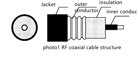
RF coaxial cable structrue
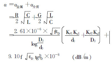
(1)
In the formula, R, C, G, L are the resistance, capacitance, conductance and electrical
Sense; α metal is metal attenuation; α medium is medium attenuation; f is frequency; εD
Is the equivalent dielectric constant of insulation; δD is the equivalent dielectric loss of insulation
Angle; D0 is the equivalent outer diameter of the insulation; d0 is the equivalent outer diameter of the inner conductor; Kρ1,
Kρ2 represents the electrical conductivity when the inner and outer conductor materials are different from the standard soft copper
Resistance increase coefficient, where Kρ = ρ/ρ0, ρ is the conductor resistivity, ρ0
It is the international standard soft copper resistivity; Ke1 and Ke2 represent the inner and outer conductors respectively
It is the increase coefficient of corrugated tube relative to smooth tube, usually Ke1,
The value of Ke2 is 1.10 to 1.20.
For the insulation equivalent outer diameter D0 in the formula, the insulation equivalent dielectric constant
What kind of parameters are established for such parameters as εD and insulation equivalent dielectric loss angle δD?
Type model and accurately determine its value, which has great influence on the attenuation calculation.
Significance. The following are coaxial cables with corrugated copper tube outer conductor
And braided outer conductor coaxial cable as an example, how to calculate the specific analysis
D0, εD, δD.
2 D0, εD, δD model determination
2.1″ Coaxial cable with corrugated copper tube outer conductor
2.1.1″ Equivalent outer diameter of insulation D0
For coaxial cable with corrugated copper tube outer conductor, due to the outer conductor
The body adopts a corrugated structure, the insulating skin layer and the copper outer conductor wave
There is also a layer of air between the peaks, and the air itself is also a kind of insulation
The medium, therefore, this will inevitably affect the electrical parameters of the cable.
Therefore, this air layer must be considered when calculating the electrical parameters of the cable
Go in, to accurately calculate the performance parameters of the cable.
Due to the uneven distribution of the air layer in the cable, the crest
The thickness of the air layer at the location is large, and the thickness at the location of the wave trough is zero.
In order to facilitate calculation, the air layer is equivalent to a uniformly distributed ring
The layer is shown in Figure 2.
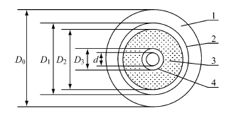
Figure 2 Schematic diagram of cable insulation structure
1-Equivalent air layer 2-Outer skin insulation layer 3-Foamed insulation layer 4-Inner skin insulation layer
The equivalent outer diameter D0 of insulation (air+insulating medium) can be adopted
Use the geometric average of the inner diameters of the crests and troughs of the corrugated copper outer conductor to approach
Approximate calculation, namely:
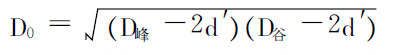
(2)
In the formula, D peak and D valley are outside the wave peak and wave trough of the corrugated copper outer conductor, respectively.
Diameter; d’represents the thickness of the copper outer conductor.
2.1.2 “Equivalent dielectric constant of insulation
From the above, it can be seen that the insulating layer is composed of inner skin, foam layer, outer skin and hollow.
The composition of the gas layer, therefore, the equivalent dielectric constant of the insulation is the four-layer string
Equivalent dielectric constant of the connection.
(1) The equivalent dielectric constant of mixed insulation εr1 (using volume plus
Weighted calculation method) calculation.
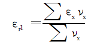
In the formula, εx is the dielectric permittivity of the insulation; νx is the mixed volume of the insulation.
(2) Calculation of the equivalent dielectric constant εr2 of the foamed insulating layer.
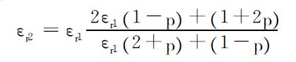
In the formula, “p” is the foaming degree of the insulation.
(3) Calculation of the dielectric constant of the equivalent insulating layer. According to capacitance
The series relationship, the relationship between the total equivalent capacitance and the capacitance with insulation is:
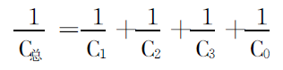
Substituting the calculation formula of each capacitor into formula (5), we can get:
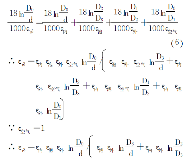
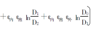
In the formula, εr3 is the dielectric constant of the equivalent insulating layer; ε inner, ε bubble, ε outside,
ε air is the insulating inner skin layer, foam layer, outer skin layer and air layer;
D1, D2, D3 and D0 are the outer diameters of each layer of insulation (see Figure 2).
2.1.3 “Equivalent dielectric loss tangent of insulation
(1) The equivalent dielectric loss tangent of the hybrid insulation tgδr1 (using
Use volume-weighted calculation method) to calculate.
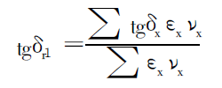
In the formula, tgεx is the tangent of the dielectric loss angle of the insulation.
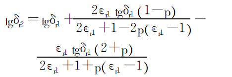
(2) Calculation of equivalent dielectric loss tangent tgδr2 of foamed insulation.
(3) The equivalent dielectric loss tangent of the equivalent insulating layer tgδr3
calculate. According to the series relationship of loss resistance, the total loss resistance is
The sum of the loss resistance of the edge layer:
Rtotal=Rinner+Rfoam+Router+Rempty
In the formula, R is always the total loss resistance; R inner, R bubble, R outer and R air are respectively
The loss resistance of each layer of insulation. Since the air dielectric loss is zero, so
The loss resistance of the air layer R air = 0, substituting into equation (10), we can get:
Rtotal=Rinner+Rfoam+Router
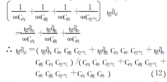
In the formula, C inner, C bubble, C outer, and C air are the insulation capacitances of each layer; tgδ inner,
tgδ bubble and tgδ outside are respectively the dielectric loss tangent of each layer of insulation.
2.2″ Braided cable
For braided outer conductor cables, the outer conductor is made of aluminum-plastic composite screen
Masking tape + metal braided wire, aluminum-plastic composite shielding tape is generally used
It is a single-sided plastic-coated aluminum, the aluminum layer is close to one side during the production process
Insulation. Due to the skin effect and proximity effect, the outer conductor
The conducted AC current is concentrated on the inner surface of the outer conductor, that is, concentrated on the
The inner surface of the aluminum layer of the aluminum-plastic composite shielding tape.
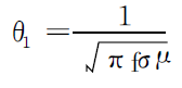
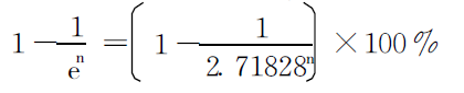
Conductor skin effect can use electromagnetic field (current) to guide the body
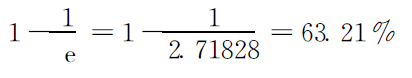
The degree of penetration is expressed as, when the internal electromagnetic field of the conductor is reduced to the surface
The depth when the value is 1/e (e = 2.71828) times the penetration depth θ1‚
Its value can be calculated by the following formula:
1 times the penetration depth is
The concentration of AC current within 1 times the penetration depth is:
The penetration depth of n times is:
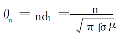
The concentration of AC current in n times the penetration depth is:
In the formula, θ1 and θn are respectively 1 and n times the penetration depth; σ is the conductor
The conductivity; μ is the permeability of the conductor. According to the above formula, in frequency
When the rate f=900MHz, calculate the current transmission through the aluminum layer
Into the depth and current concentration (see Table 1).
Table 1 f = 900MHz when the penetration depth of the aluminum outer conductor and
Current concentration degree [2]
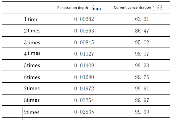
It can be seen from Table 1 that when the frequency is 900MHz, the thickness of the aluminum layer
When the penetration depth reaches 5 times the penetration depth of the current, the AC current will have
More than 99% of the current is concentrated in the aluminum layer. This penetration depth can
Ensure the transmission characteristics of the cable. In the actual manufacturing of cables, usually
The thickness of the aluminum-plastic composite shielding tape used is 0.035mm, in which the aluminum layer
The thickness is 0.020mm, when the frequency is 900MHz, the thickness of the aluminum layer
More than 7 times the current penetration depth, which can guarantee 99.9% of the electricity
The flow can be concentrated in the aluminum layer for transmission. It can be seen from equation (13) that
The higher the frequency, the more obvious the conductor skin effect. It can also be said that the current 2G
The 1800MHz frequency band used and the 2000MHz that 3G will use
The above frequency bands, the skin effect is more obvious, and the transmission effect is better.
The coating layer of the aluminum-plastic composite shielding tape is a layer of insulator; metal
The main function of braided wire is shielding and does not participate in the transmission of AC current.
For braided cables, in fact, the outer conductor is only aluminum-plastic composite
The aluminum layer in the shielding tape.
The attenuation calculation of braided cable can also be calculated by formula (1), but relative to
For the corrugated outer conductor coaxial cable, the equivalent insulation layer has no air layer.
Accurate calculation of coaxial cable attenuation, design and development of cables,
The quality control of cables is of great significance. For wrinkled copper tubes
For the outer conductor coaxial cable, you can slightly adjust the cable
Structure to control the attenuation. Of course, the premise is that the electricity cannot be affected.
The installation and use of the cable, for example: it can be ensured that the conductor
These parameters directly affect the cable installation
Under the components, it is appropriate to change the outer diameter of the insulation or the depth of the trough of the outer conductor, etc.
Factors to adjust the attenuation parameters of the cable. Also need in the design and production process
Other electrical parameters such as impedance, standing wave, speed ratio, and cable adjustment should be considered.
Body structure stability, etc.
Cable attenuation is an important indicator to measure the level of cable quality.
It is the foundation to ensure the optimization of theoretical attenuation in the cable structure design stage.
At the same time, the impact of other factors on the attenuation of the finished cable cannot be ignored.
Noise, such as the return loss caused by the unevenness of the cable structure.
Causes the cable attenuation to deteriorate; the cable and the design match poorly
Wave loss, lead to large cable test attenuation; raw material quality, temperature
The influence on attenuation and other factors may make the actual test of the cable
The attenuation is greater than the theoretical attenuation.
For more questions, you are welcome to contact zhuhai hanqin cable co.,ltd or email: info@hanqin-cable.com